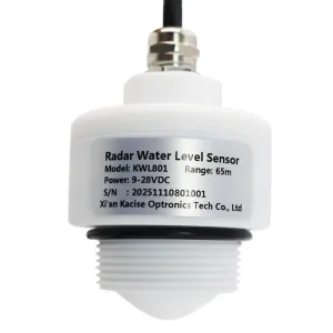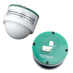




1. What Is a Radar Level Sensor & How Does It Compare to Traditional Options?
Radar level sensors are core instruments for industrial liquid level measurement, developed based on millimeter-wave technology (76GHz~81GHz).Featuring non-contact measurement, high integration, compact size, and flexible interfaces, they can penetrate light, rain, dust, fog, or frost-enabling all-weather operation, which solves the limitations of traditional sensors in harsh environments.

Below is a detailed comparison between radar level sensors (KLM800/KWL801/KWL802/KWL803 series) and traditional alternatives, based on official product specifications:
| Feature | KACISE Radar Level Sensor | Float-Type Level Sensor | Ultrasonic Level Sensor |
| Measurement Principle | FMCW | Buoyancy-driven mechanical movement | Sound wave reflection |
| Accuracy | ±1mm–±2mm (KWL801: ±1mm; others: ±2mm) | ±10mm (easily affected by mechanical wear) | ±0.5~1%FS |
| Measurement Range | 0.06m–70m (KWL801: 0.1m–70m; KWL803: 0.06m–40m) | Limited (max 20m) | 0.2m–30m |
| Media Compatibility | Resists corrosion, foam, dust, fog; fits liquids/solids | Prone to jamming by viscous/abrasive media | low dielectric constant material(complementary to radar) |
| Communication Protocol | Modbus-RTU, Text Protocol (AT commands), TTL/RS485/RJ45 | None | Modbus-RTU, TTL/RS485 |
| Protection Rating | IP67 (KWL801), IP68 (KWL802/KWL803) | IP65 (needs frost protection) | IP65~IP68 |
| Operating Temperature | -40°C–85°C (KWL801), -40°C–75°C (others) | -20°C–80°C | -40°C–85°C |
2. Radar Level Sensor Product Parameter Comparison Table
Based on KACISE’s official product documents (KLM800/KWL801/KWL802/KWL803 series), the following parameter table helps you quickly match models to needs:
| Parameter | KLM800 | KWL801 | KWL802 | KWL803 |
| Operating Frequency | 80GHz | 80GHz | 80GHz | 80GHz |
| Measurement Range | 0.06m–3m / 0.15m–20m / 0.4m–40m | 0.1m–12m0.3m–65m | 0.06m–3/5/10m; 0.1m–15/20m;0.2m–40m | 0.06m–3/5/10m; 0.1m–15/20m; 0.2m–40m |
| Measurement Accuracy | ±2mm | ±1mm | ±2mm | ±2mm |
| Beam Angle | ±3° | 6° | ±2.75° | ±2.75° |
| Communication Interface | TTL (Modbus) | RS485 (Modbus-RTU) | RS485/RS232/RJ45/TTL (Modbus/Text Protocol) | RS485/RS232/RJ45 (Modbus/Text Protocol) |
| Power Supply | 3.3V DC | 9V–36V DC | 9V–24V DC | 9V–24V DC |
| Protection Rating | IP65 | IP68 | IP68 | IP68 |
| Operating Temp | -20°C~70°C | -30°C~70°C | -40°C~75°C | -40°C~75°C |
| Key Features | Compact size; low power (1.5mA standby) | 65m high measure range | IP68 waterproof; AT command support | IP68 waterproof; AT command support |
Kacise Radar Level Sensor Selection Guide: Radar Level Sensor Selection Guide-EN.pdf
2.1 How to Choose the Right Radar Sensor?
Step 1: Match Medium & Model
Corrosive media (acids/alkalis): Choose KWL801/KWL802 (IP68, 316 stainless steel/PTFE lining).
Foamy/turbulent media: KWL801 (5GHz bandwidth) penetrates foam layers effectively.
Step 2: Align Tank Size with Range & Beam Angle
Narrow wells/small tanks (diameter <1m):KWL802 (±2.75° beam angle).
Large reservoirs/tanks (diameter >5m): KWL801 (0.3m–65m range).
Warning: Avoid mounting near agitators or riverbanks—ensure beam paths are unobstructed.
Step 3: Confirm Environmental & Process Conditions
Humidity/Submersion: IP68 (KWL801/KWL802/KWL803) for high humidity or flood risks.
Power Supply: KLM800 (3.3V) for low-power setups; KWL801 (9V–36V) for industrial power systems.
Step 4: Verify Compatibility & Maintenance
Communication: Ensure the sensor supports your system protocol.Maintenance: Clean the antenna with alcohol every 3 months (per KACISE’s recommendation) in dusty environments—this reduces failure rates by 80%.
If you are unsure which model to choose, feel free to contact us with your application details for technical support.
3. Key Parameter Explanations
3.1 Measurement Range

The measurement range refers to the minimum and maximum distance a radar level sensor can reliably measure between the sensor and the liquid surface. It is typically expressed as a range (e.g., 0.3m–65m), indicating the sensor’s effective working scope—any liquid level beyond this range will result in inaccurate readings or no data output.It’s critical to match the range to your actual monitoring needs: a sensor with a 40m range works for shallow wells, while large reservoirs may require a 65m range to cover full water level fluctuations.
3.2 Blind Zone
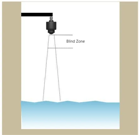
The blind zone is the minimum distance immediately below the sensor where it cannot detect the liquid surface. Due to signal limitations, the sensor fails to generate valid measurements for liquid levels within this zone.For example, if a sensor has a 0.3m blind zone, it cannot accurately measure liquid levels closer than 0.3m from the sensor—this is crucial for shallow water monitoring scenarios.
3.3 Beam Angle
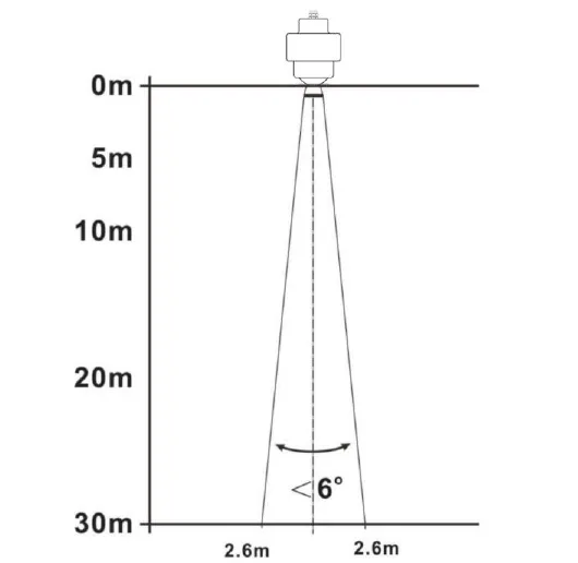
The beam angle is the width of the electromagnetic wave beam emitted by the sensor. It determines the sensor’s “detection coverage”—a narrow beam angle (e.g., ±2°–±4°) focuses the signal on a small area, reducing interference from obstacles like tank walls or riverbanks. A wide beam angle (e.g., 8°–22°) covers a larger area but is more prone to false echoes.Narrow beam angles are ideal for narrow wells or cluttered environments, while wide angles suit open reservoirs.
3.4 Communication Interface

The communication interface is the physical port or protocol through which the sensor transmits measurement data to external devices (e.g., controllers, monitors, or wireless modules). Common interfaces include RS485, TTL, RJ45, and corresponding protocols like Modbus-RTU or text protocols (AT commands).RS485 is widely used for industrial on-site communication, while RJ45 supports network/wireless transmission (e.g., 4G DTU) for remote monitoring.
4. Application Scenarios
4.1 Water Conservancy & Wastewater
Scenario: River/reservoir flood monitoring, sewage tank level control
Recommended Models: KWL801 (0.3m~65m range);KWL803
Why: KWL801’s 65m long range suits large reservoirs; KWL803’s IP68 resists sewage corrosion and submersion.
4.2 Chemical & Petrochemical
Scenario: Corrosive chemical tanks (e.g., sulfuric acid), crude oil storage
Recommended Models: KWL801/KWL802 (PTFE-lined antenna)
Why: IP68 protection prevents chemical leakage damage; Modbus/Text Protocol enables remote monitoring.
4.3 Customized Development & Secondary Integration
Recommended Model: KLM800_TTL (compact size, 3.3V low power)Why:Small size, low power consumption,It can be compatible with different casings.